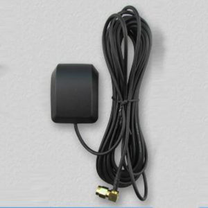
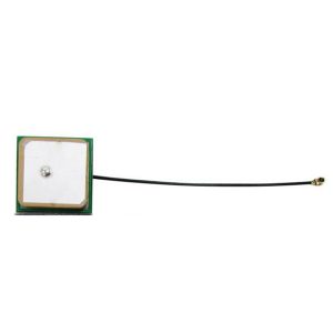
Dual Band L1 L5 NaviC GNSS Antenna for Enhancing the GPS Device Signal
Stable Performance NaviC supported GPS GNSS Antenna with SMA Male Connector for Enhancing GPS Tracking device signal.
Overview
GNSS antennas are a critical but often overlooked part of a receiver setup. Choosing a correct antenna is hugely importantsince antennas are the main interface between the GNSS space segment and the user, as they capture the L-band signatransmitted by satellites. Antenna must be able to convert the energy in the electromagnetic waves arriving from thesatellites into an electric current that is further processed by the receiver. Given that signals received from GNSS satelliteare weak and arriving trom any direction, it is clear that choosing the correct antenna is imperative, choosing the optimaGNSS antenna for the application will maximize GNSS receiver’s positioning performance.
The HGA3525 active antenna are use HoneyComm unique technology to achieved GNSS dual band system operation, thatcan covering the GPS L1,L2,5: BeiDou B1,B2 frequency band. in order to meet simple foot print layout on main board andlow cost demand, HoneyComm use stack with one feed pin of antenna to generate two frequency mode, which are stilshows the low axial ratio and RHCP polarization radiation performance. iThe operation band of patch element can bechoosing by customer demand]
In order to increase GNSS radio frequency sensitivity and siqnal noise ratio, HGA3525 uses a LNA+ Dual SAW+PD+LNAdiagram, which provides excellent noise figure and high gain that is constant across the full freguency band, The finaoutput with the SMA female connector, it’s easy to fit together with RF cable.
The HGA3525 active antenna has portable and dual band features, which can use on tracker, navigation device andautonomous vehicles.
Features
One pin feed in
low AR
Support dual band system
Multi-band GNSS reception
LNA gain 28 dB typ.
High rejection SAW filter
Low noise figure <2dB
Specification
| Parameter | Specification |
|
Support system |
GPS: L1, L1C, L5C BDS: B1I, B1C, B2a
Galileo E1, E5a QZSS:L5 IRNSS: S-L5 |
| Antenna architecture | One pin feed |
| Antenna dimension | 25x25x4mm for higher band
35x35x4mm for lower band |
| Polarization | RHCP |
| Axial ratio | Max 3.0dB@zenith |
| Antenna peak gain | 2.68dBi for higher band(with35x35mm GND)
1.98dBi for lower band (with35x35mm GND) |
RF Performance
| Parameter | Specification | |
| LNA gain | 28 dB typ. at all operation band on 3.3V | |
| Noise figure | ≤2dB | |
| Output SWR | <2.5 | |
| Output impedance | 50 Ohm | |
| Out-band rejection | Higher band | In-band ±50MHz>30dB |
| lower band | In-band ±50MHz>30dB | |
| Support voltage | 2.5-5.5V / 3.3V typ. | |
| Power consumption | <15mA at 3.3V | |
| ESD protection | IEC61000-4-2(ESD), 18KV(air),18KV(contact)
IEC61000-4-4(EFT) 40A(5/50ns) |
|
Mechanicals and Environment
| Parameter | Specification |
| Dimension | Diameter 59.7mm x 56.7x Height 21mm |
| Operation temperature | -40° to +85° |
| Relative humidity | 40% to 95% |
| Environment | ROHS and REACH |